Use Cases
Industrial case studies that will benefit of MegaM@rt2Use Case Provider: Thalès France
Industrial Domain: Flight Management System
Context
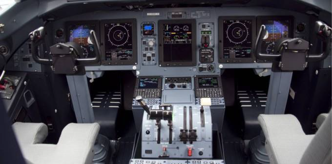
The case study selected by Thales is a Flight Management System (FMS). It is an industrial avionics application whose purpose in modern avionics is to provide the crew with centralized control for the aircraft navigation sensors, computer based flight planning, fuel management, radio navigation management, and geographical situation information. Taking charge of a wide variety of in-flight tasks, the FMS allows to reduce the workload and thus the size of the crew. This avionic function is responsible for the flight management services allowing inflight guidance of the aircraft through optimized trajectories computations.
The application is representative of a commercial Flight Management System and has been redesign and rewritten in a multi-threaded way so that the application can be executed in a distributed way. Even if it is a simplified version of a Flight Management System, the application is still representative of avionics application in term of performance and memory requirements.
Challenge
The figure above gives a functional overview of the Flight Management System. This application is responsible of the Inflight guidance of aircrafts based on the use of flight plans. Merging sensors information allows the application to evaluate the plane’s localization, which together with the pre-set flight plans allows computing some trajectories that will be translated into guidance actions to guide the plane.
In the current approach, Thalès applies Model-based systems engineering for a component based design and UML for detailed implementation; use of in-house code generators for up to 40% of the source code, verification and testing. The main challenges are linking development models and verification and validation activities, test case generation of performance test cases, architecture analysis, model-based tools collaboration.
MegaM@rt2 Benefits
With MegaM@Rt, Thalès intends to reduce the effort for verification and validation while preserving quality and performance. MegaM@Rt will contribute to overall improvement of the development process.
Use Case Provider: IKERLAN
Industrial Domain: Digital Platform for Smart-*
Context
During the last years IKERLAN has been working on several projects for the development of different platforms for monitoring, control and supervision of remote IoT devices. These platforms have been used in different industrial and non-industrial environments, i.e. smart warehouses, smart buildings, smart manufacturing, consumer goods, etc.
Trying to avoid repeating similar work in each project, IKERLAN is going to develop a generic system that can be accessible and useful for a plethora of industrial companies (different domains and applications) with different functional and extra-functional
requirements. This could allow to have a system that could be easily adapted to many industrial domains, having a set of core technologies reused in every project.
Due to the complexity of developing a generic IoT device management ecosystem with these characteristics, it is vitally important to have a platform lifecycle process (embedded devices and the cloud) that guarantees product quality, security and reliability. In this way, IKERLAN is going to improve their IoT device ecosystem lifecycle process: focusing on the relation between the design time and runtime, also taking into account the verification and validation processes in a continuous way, reducing costs without losing quality.
Challenge
As described above, the IKERLAN-KONNEKT platform consists of several devices within the entire value chain for monitoring, controlling and supervising remote IoT devices. Based mainly on embedded devices at edge or fog and the cloud supervision system, IKERLAN poses the following challenges for the MegaM@Rt2 project:
- Include in the system model the infrastructure data used by all components of the monitoring system. This will make it easier to maintain and reuse the model for other application domains.
- Automatic generation of model-based code that will speed up the development task
and make it more secure. - Automatic generation and execution of tests so that they can be detected in early stages of development and that they can be automatic in order to validate them against different domains and applications.
- Runtime verification that based on different log traces generated by the system will allow to observe, detect and even react to unexpected behavior or violations of non-functional properties of the system.
- All this is part of a continuous development process that will allow us to improve
product quality and reduce costs.
MegaM@rt2 Benefits
With MegaM@Rt, IKERLAN aims to improve the different phases of the life cycle of the projects it carries out for companies in various sectors. The final aim is to improve both the efficiency of project development and the quality of the projects.
Use Case Provider: CAMEA, spol. s r.o
Industrial Domain: Intelligent Traffic Surveillance System
Context
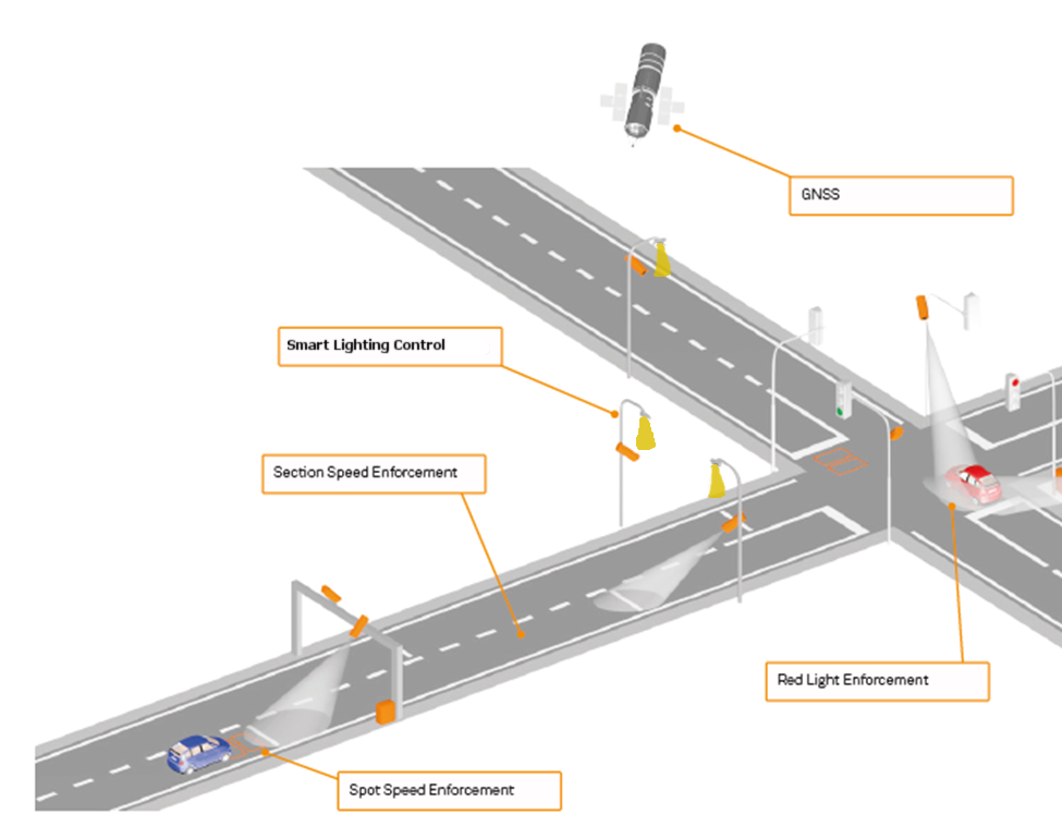
UnicamVELOCITY is a CAMEA’s solution for section speed enforcement (also called section, point-to-point or average speed control or check). When compared to spot speed enforcement systems (radars, inductive loops, LIDARs etc.) which only measure the actual speed in one place, the main extra feature is that the average speed of the vehicle is measured in the entire specified section. The system has been certified for speed enforcement.
The principle of the averaging speed measurement is simple, there are two camera equipped sites with the know, well measured distance between them. As they can be tens of meters or couple kilometre far, the precise time synchronization could be an issue. Using global navigation satellite system seems as the best option. Video-based detection is continuously performed (using detail cameras) and LP for each passing vehicle is being detected and subsequently read using specialized OCR algorithm. The detected LPs are then matched and when match is found, the average speed is calculated based on the known distance travelled and time elapsed (between the two detections). Then, it is usually compared with the limit set and a violation report could be generated.
The UnicamVELOCITY system is composed as a combination of a local processing on site (LP detection and OCR) with all the infrastructure around (video cameras, IR flashes, PC, networking, etc.), and background processing running on server side.
CAMEA uses multiple levels of processing in its system. Part of the computation is done locally and the rest is done on the server. Currently, on the sites Unicam systems use Ethernet cameras (manufactured by CAMEA) wired to computationally powerful PCs capable of running powerful video detection algorithms. The detector also supports additional logic e.g. for controlling IR flashes on demand/trigger. The detection results are then sent to the server computer and processed in the meaning of the matching corresponding detection and calculating average speed. When speed limit is violated, detailed evidence images can be requested from the site (which saves network bandwidth).
CAME Use Case
Challenge
Powerful computational machine is often advantage, however, there are often needs for decreasing power consumption of the system as whole. The site does not always have a stable power supply and the system has to be then battery powered. In case of public lightning present, the batteries can be recharged overnight. Sometime there is no power supply at all and batteries has to be big enough to allow couple day of system’s operation and then the whole battery pack has to be changed. Even heat dissipation could be a big problem when the computer running in hermetically sealed box (weather resistant) without active cooling.
At this point, use of smaller computers or even all-in-one solutions in form of cameras with embedded intelligence (in case of CAMEA build on the basis of Xilinx Zynq chip) is big advantage. The question is, how to port all the field-proven applications to the new platforms including often different division of algorithm parts over the system. For the smart camera, most time-critical part of the algorithm, such as LP detection, can be moved to the FPGA (e.g. FPGA part of popular Zynq chip) and simple post processing and sending detection results will be then executed in CPU (or CPU part of Zynq). On the server side, OCR algorithm can be executed (over the cropped image with LP present) and all the matching is then done in the same manner.
It is obvious that this way the energy consumption of the on-site system part has been reduced and part of the computation load has been transferred to the server. But still keeping low network load very low. The biggest question is how to easily transfer all the algorithms and services to other (often hybrid) platforms including moving part of the processing load to the cloud.
MegaM@rt2 Benefits
With application of the MegaM@Rt2 framework CAMEA is expecting simplification of the development process in form of reducing the total design time of new components of intelligent cameras and other devices. It is as well expected to support finding an optimal division of the functionality between “on-board” of the available HW and “offload” computation in the cloud (with respect to the modelled computational power available and other efficiency aspects). The it is also possible to reach optimal ratio of computation power/power consumption/price. The MegaM@Rt2 framework can be also used in optimisation of code run-time, e.g. for static scheduling of tasks (based on profiling) employing process priorities.
CAMEA will directly exploit project result in its everyday business products linked to the image processing and advanced computer vision. Specialised, safety critical components responsible for red-light and speed camera measurements will be employed in solutions outside the main MegaM@Rt2 line and the process of their development will benefit from reduced failure rate due to better detection and analysis of potential sources of failure.
Use Case Provider: AinaCom
Industrial Domain: ICT Services
Context
The case study selected by AinaCom is a SMS Gateway application. The general purpose of the Aina SMS Gateway application is to deliver a mass of SMS messages from the service providers (public administration offices, super market chains, car service chains etc) to the SMS recipients (end users) and also deliver possible responses from the SMS recipients to the service providers.
MegaM@rt2 Benefits
We expect with methods and tools of MegaM@RT2 project to help setting up testing automation environment with auto generation of module and system component test cases. We also expect MegaM@RT2 to deliver methods and tools for the run-time analysis to improve the functionality of SMS Gateway and to enable simulation of service providers, tele operators and mobile users in the test automation environment.
Use Case Provider: Bombardier Transportation
Industrial Domain: Automation/Automotive
Case Study Overview
The BOMBARDIER MITRAC Train Control and Management System (TCMS) is a high capacity, infrastructure backbone built on open standard IP-technology that allows easy integration of all control and communication requiring functions on-board the train. TCMS is the centre of the distributed system that controls the train. TCMS is involved in almost all train functions either in a controlling or supervising capacity. Examples of train functions include collecting line voltage, controlling the train engines, opening and closing the train doors, and uploading diagnostic data. The different intelligent units of TCMS are connected to each other and the other intelligent units on the train via different communication links, such as MVB and IP networks. The TCMS development processes have to conform to the EN50128 standard for development of railway control software in order to obtain a certain Safety Integrity Level (SIL).
MegaM@rt2 Benefits
Need for MegaM@RT2t solutions: Main TCMS development process areas in high need of improvement:
- Platform and Variability Management concerns the investigation of innovative and automated ways to cope with variability in the development of the TCMS system. The expectation of MegaM@RT2 is to provide methods to support the develop a Platform Management System that can handle the configurability of the overall TCMS system, including requirements documentation, design documentation, test artefacts, artefacts needed for assessment, etc.
- Architecture and Traceability Management concerns the investigation of efficient traceability support between architecture, design and runtime artifacts.
- Model-Based Testing concerns the investigation of innovative methods for test case generation, test case selection, and test results evaluation.
Use case Provider: Volvo CE (VCE)
Industrial Domain: Transportation/Construction
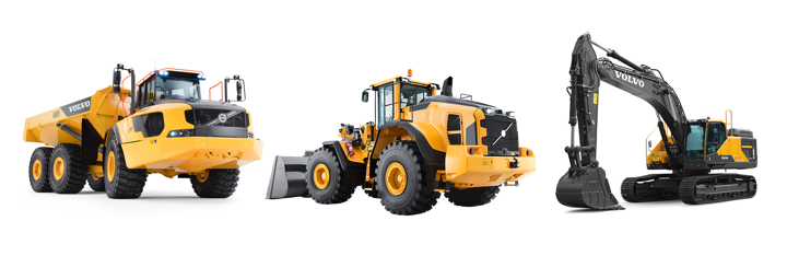
Volvo CE (VCE) develops, manufactures and markets equipment for the construction and related industries. The vast product range of VCE includes different types of loaders, excavators, trucks, forestry machinery and demolition machinery. VCE has a 180-year-old engineering heritage, with emphasis on quality, comfort, safety and control. Volvo CE’s mission is to produce high quality, safe and environmentally-friendly machines that meet customer needs. VCE has a commitment towards innovation in different sectors, such as productivity, safety, uptime and fuel efficiency. VCE continues to invest money in advanced engineering solutions to improve current technology, such as supporting automated and semi-automated functions. In their engineering process, VCE are striving towards an end-to-end model-based system engineering MBSE) lifecycle with associated tool support and traceability engineering. In MegaM@RT2, VCE will provide a case study in the automotive domain, focusing on VCE’s electrical and electronic system, particularly the engine control subsystem and other related domains focusing towards adopting MBSE methodology. The case study will enable comparative evaluation of model-based approaches. Furthermore, the case study will include features covering both design and runtime aspects and therefore will help evaluate if a future VCE product design matches the desired runtime behavior.
Expectations from MegaM@Rt2
Variability Modeling:
The engine controls subsystem and the engines used by VCE are calibrated for each machine individually. The engines are also designed and configured in a way that suits VCE machine needs. In order to calibrate and set the correct values (for roughly about 10.000 parameters), tests are run in both rig and machine. In this context, VCE intends to investigate if it is possible to:
- a) Manage product families such that the same parameter set can be used to the greatest extent possible.
- b) Express different configurations in the model.
- c) Model engine variants, such that different types of machine development teams can be provided with engine system models, capturing the engine behavioural requirements.
- d) In the extension, reach a point where executable specifications can be modelled and expressed.
These could, for example, be used in communication with subcontractors.
Testing:
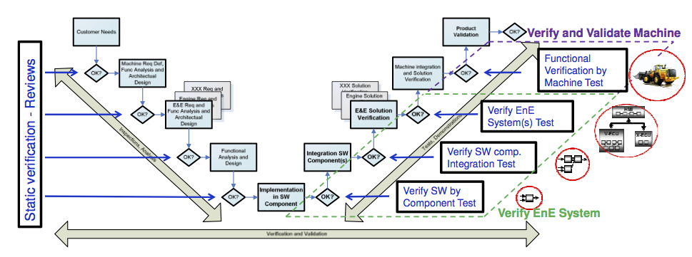
The traditional V-model well describes VCE’s current development process from requirements to validation of the final product. This model is a concept for describing validation and verification activities at Volvo CE through the different phases of software development. Validation and verification activities are conducted in different levels that correspond to a specific phase during development. The right leg is divided in four main test levels: component test, integration test, system test on electronic test rigs and verification of functions in machine (named machine test in the V-model) i.e. integration of electronics system (Figure below).
For each level in the V-model, there is a validation activity that can be done on the left side of the model, i.e., the development process. For every level, it is possible to validate that the user or business requirements are fulfilled and that the actual design level has enough detail to realize the next level. For example, the functional requirement specification shall correspond to the system requirement specification and have enough detail to be able to realize the software architecture design specification. At the right side of the V-model, there is a corresponding verification activity at each level of the development phase. For early detection of potential defects in the requirements, which will lead to faults in the implementation, each requirement level is reviewed from a different stakeholder perspective. As every level in the left leg of the V-model is completed, planning of verification activities shall start for the corresponding level in the right leg.
With the help of Megam@RT2, VCE intends to work towards a more iterative and continuous process, based on virtual integration and simulation. In the context of Megam@RT2, this work will be initiated with the Engine Controls department.
Use Case Provider: Nokia Solutions and Networks
Industrial Domain: Telecommunication
Nokia focuses on the base station SW/HW co-development process from the product and organization point of view.
The base station architecture enables various HW and SW configurations from small size picocell to huge server clouds. The goal is to create an integrated workflow toolchain (see figure below) from a platform independent perspective to facilitate integration of various subsystems and verification of the overall system performance to meet a set of desired system requirements and at the same time taken account the ever-increasing system complexity. In addition, there will be formal linking between the requirements, the architecture/design documents, test, and verification results.
Challenge
Using the MegaM@RT2 workflow toolchain, the target is to achieve support for Software architectures that capture the essences of an application and platform domains. Architectures of this general nature should include aspects such as functional components, their relative control and communication relationships, as well as non-functional aspects such as scalability, security, fault tolerance, and maintainability. MegaM@Rt2 workflow toolchain should support following needs:
- Megamodelling tools and processes to improvement modelling process for different architectures from small size to cloud solutions.
- Tools and methods to setup measurable acceptance criteria of interfaces between architecture blocks.
- Advanced data visualization tools and effective analytics algorithms for the shorter feedback loop.
- One model method to Shift Left testing and verification & validation.
- Modelling language for integrated hardware and software modelling.
MegaM@Rt2 Benefits
Usage of the MegaM@Rt2 workflow toolchain offers following benefits:
- Extensive use of models, especially producing validation information from models
- Early validation, fast validation cycles
- Automation instead of manual work
- Better visibility to the state of e.g. system or feature both in development and runtime
- Better utilization of measuring points defined in models as well as the data gathered from the usage of the system