Specifying the architecture of such a large project as MegaM@Rt2 (27 partners from 6 different countries, 9 industrial case studies as well as over 30 different tools from project partners) is a challenge in itself. We opted for a pragmatic model-driven approach in order to specify the case study requirements, design the high-level architecture of the MegaM@Rt2 framework, perform the gap analysis between the industrial needs and current state-of-the-art, and to plan a first framework development roadmap accordingly.
We believe that our experience and lessons learnt in the process could be useful in other similar contexts. A paper summarizing those has been accepted at the SEDA conference. The paper concentrates on the concrete examples of the tooling approach for building the framework architecture. In particular, we discuss the collaborative modelling, requirements definition tooling, approach for components modelling, traceability and document generation.
If you’re not attending the conference, keep reading to see the MegaM@Rt2 tool integration and architecture building approach.
1. MegaM@Rt2 toolsets
The MegaM@Rt2 framework plans to integrate more than 30 tools. The tools features are grouped in three conceptual tool sets
- MegaM@Rt Systems Engineering Tool Set regroups a variety of current engineering tools featuring AADL, EAST-ADL, Matlab/Simulink, AUTOSAR, Method B or Modelica, SysML and UML in order to precisely specify both functional and non-functional properties. Moreover, system level V&V and testing practices will also be supported by this tool set.
- MegaM@Rt Runtime Analysis Tool Set seeks to extensively exploit system data obtained at runtime. Different methods for model-based V&V and model-based testing (MBT) will be rethought and/or extended for runtime analysis. Model-based monitoring will allow to observe executions of a system (in its environment) and to compare it against the executions of corresponding model(s). Monitoring will also allow a particular system to be observed under controlled conditions, in order to better understand its performance.
- MegaM@Rt Model & Traceability Management Tool Set is a key part of the framework as it is dedicated to support traceability between models across all layers of the system design and execution (runtime). This can go from highly specialized engineering practices to low-level monitoring. Relying on the unification power of models, it should provide efficient means for describing, handling and keeping traceability/mapping between large-scale and/or heterogeneous software and system artifacts.
2. Architecture Specification approach
Model-based approaches for specification have been developed consistently during almost two decades [8]. Automated document generation was one of the first benefit offered by the Model-driven Architecture (MDA) [3,8]. Indeed, models as the first-class entities of the engineering process should contain all the necessary information for the design documentation. However, several challenges arise. First, the architect team should decide the right organization for the global architecture model. Second, it should be carefully planned which level of details is appropriate for the design of the individual contributions. Third, it should be considered that the architecture model will be used during 3 years of the project for numerous purposes, and thus needs to be prepared to accommodate for changes in methodology. Fourth, several documents need to be generated by extracting the relevant information from all over the architecture model.
We adopted a practical approach for the architecture specification that is particularly adapted to collaborative projects such as MegaM@Rt2, thus integrating tools coming from several parties. As modeling language, we took a Systems Modeling Language (SysML) [4] subset for requirements specification and a Unified Modeling Language (UML) [5] subset for the high-level architecture specification. We splitted the architecture model in several parts and divided the responsibilities among the different Work Package (WP) leaders, tool providers and case study providers (see Fig. 1) :
- Requirements, specified in SysML
- Case study requirements – specified by case study partners,
- Framework requirements – specified by WP leaders,
- Tool purposes – specified by tool providers
- Architecture, specified in UML
- Framework – each conceptual tool set specified by WP leaders
- Tool set – each tool specified by tool providers
- Common interfaces – specified by tool providers
- Common deployment frameworks – specified by tool providers
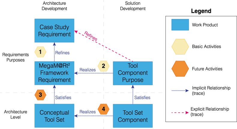
The approach to define the MegaM@Rt2 framework architecture is depicted in the figure above. At the Requirements Purposes level, we identify the needs of industrial partners in the form of Case Study Requirements and from them we extract (Activity 1) generic MegaM@Rt2 Framework Requirements. For the latter, we identify (Activity 2) a set of Tool Component Purposes that will realize the case study requirements. At the Architecture level, each Conceptual Tool Set component and the relevant interfaces are identified (Activity 3) to satisfy framework requirements. Then, for each Conceptual Tool Set Component we specify (Activity 4) concrete tool set components to realize the desired functionality. Those concrete tool set component expose features and satisfy purpose requirements that include the release milestones indications for the roadmap definition.
3. Tooling approach
Appropriate tooling support is important for the success of the model-driven engineering process shown in Fig. 1. In order to provide tool support for our architecture specification approach, we selected the Modelio and Constellation tools provided by one of the project participants, SOFTEAM.
When collecting inputs of 50 users, it was important to provide guidelines and diagram templates. Otherwise, the integration work may become extremely challenging. As such, we defined a set of template diagrams both for specifying requirements and for collecting tool purposes. Users were able to clone these templates inside the model to describe their concrete tools.
In the next subsections we are providing more details on how different features of the tool were used to support our approach.
3.1 Architecture specification
Modelio is an MDE workbench supporting standard modeling languages such as UML, SysML among others. All the modelling notations can be used in the same global model repository which is important for model traceability and management.
Requirements modeling. In our approach, requirements originated from different sources, i.e. from 9 case study providers and 22 tool providers. In order to have an uniform approach for requirement specification that would facilitate gap analysis and roadmap identification, we defined requirement templates that were used to define the expected properties to be collected, such as criticality for the case study requirements and planned release date for tool purposes. Modelio allowed us to edit requirements in both diagram view and tabular view (see Fig. 2). The requirements were manually edited or automatically imported from other documents, e.g. MS Excel.
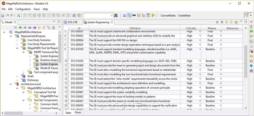
Fig. 2. Requirements editing with Modelio
Architecture modeling. On the architecture level, we used Class and Deployment diagrams. We limited modelling to a subset of UML to enforce the common understanding of the architecture and simplify editing. In particular, we choose to use UML Components, Interfaces, Associations, Generalizations and Dependencies.For tool components, we set a template for the architecture specification that included class diagram to specify functional interfaces, tool components subordinates and the relation to the conceptual tool set in the framework, and deployment diagrams to identify the execution environment of the tool component. In addition, Package diagrams have been used to define the high level structure of the MegaM@Rt2 framework architecture. For instance, Fig. 3 shows that the MegaM@Rt2 framework architecture is composed of three parts corresponding to the three WPs of the project. System Engineering, Runtime Analysis, and Model and Traceability Management, respectively.
In Modelio, the documentation (Fig. 3) can be added in the textual notes or attached as separate documents. Both plain text and rich text notes are supported. In our work, we deliberately restricted editing to plain text notes to make sure that the generated documents are formatted correctly.
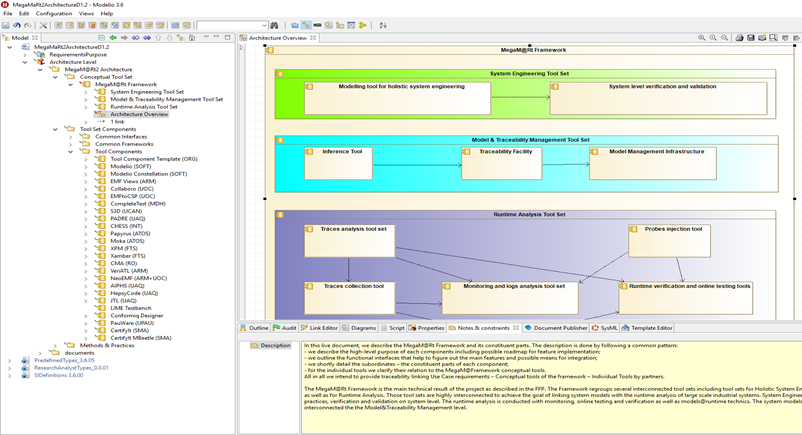
Fig. 3. Editing architecture and documentation with Modelio
Requirements traceability. Once the requirements have been specified, for each tool component we defined a traceability matrix to link case study requirements to framework requirements, and respectively framework requirements to tool purposes as depicted as described by Activities 1 and 2 of the modelling approach in Fig. 1. This allowed us to use instant traceability diagrams, as the one in Fig. 4, to visualize the whole set of dependencies for a given requirement. This proved beneficial not only for the requirement analysis and toolset integration planning, but also for identify common interfaces for tool components and visualize gaps for the requirements analysis.
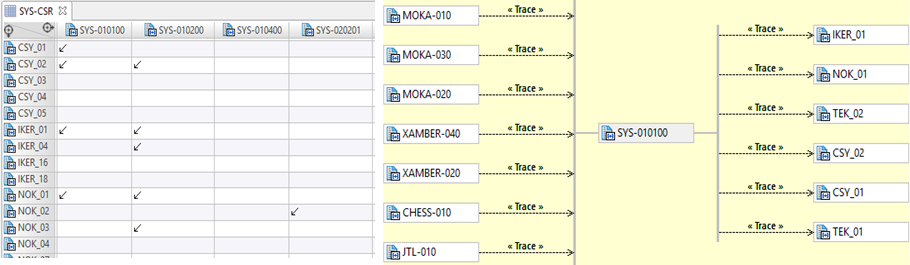
Fig. 4. Example: Traceability links among the tool set, framework and case study requirements
Generating documents. Modelio offers fairly flexible model query and document generation facilities that were used for editing and maintaining four specifications in the project. The template editor (Fig. 5) was particularly useful to implement custom extraction of model elements in order to create specific sections of the document. In the example below, the template specifies that the generator will search for a Tool Components package, look at all the UML components to generate a tool section. This document section will include introductory paragraph, “Purpose” subsection, subsections for all class and deployment diagrams as well as section on the owned interfaces.
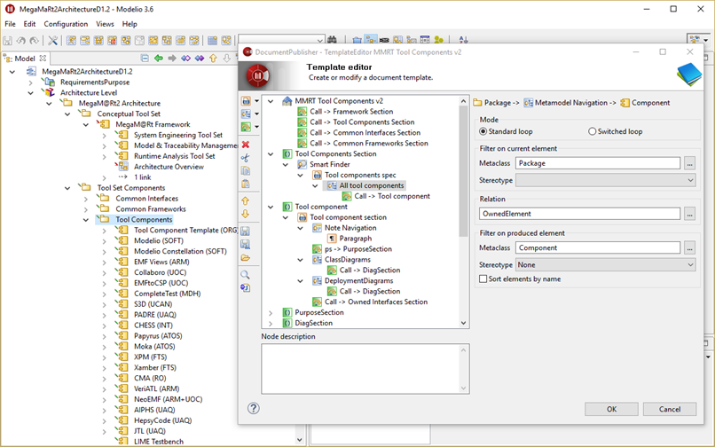
Fig. 5. Example: Custom document generation template for individual tools section.
When editing the architecture model, it is quite useful to see the generation result. Along with developing custom document templates, we integrated the document generation to the Modelio interface. That way regular users could call the document generation directly from the tool using a context menu (Fig. 6).
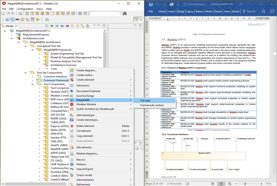
Fig. 6. Example: Architecture document generated with Modelio Document Publisher.
3.2 Collaborative model editing
Modelio Constellation [12] is the model sharing, collaborative editing, versioning and configuration management facility that allow hundreds of modellers to work together on the same common and shared model. Indeed, authoring architecture deliverables in MegaM@Rt2 project required contributions of 27 partners. Thus, around 50 users worked together on the single model. On the regular basis, users connected to the Constellation server, synchronised the local model with the central repository, edited the architecture and generated the documents with alway updated templates. The documentation templates and user interfaces for document generation were developed continuously and had to be rolled out to the whole large team of modellers without interrupting the work process. It was important to provide versioning and conflict resolution when editing touched the common artifacts. Last but not least, several different deliverables were generated out of the same model. Therefore, the branching facility allowed to fix the state when the deliverable was released.
4. Conclusions
In this paper, we presented the tool support we used in order to specify the architecture of the MegaM@Rt2 framework using model-driven principles and practices. Our approach enforced the coordination and collaboration among many different stakeholders and thus manageability of this complex project. Indeed, the main benefits of our model-driven approach are that all information was collected from different stakeholders and stored using one single into one single model using one single tool. This model was used as a central repository, which every project partner updated or accessed using model versioning techniques. In addition, having all the information in one single place, allowed us not only to constantly monitor the status of the process and to trace the requirements of the framework components, but also to easily generate necessary artefacts (such as documents, tables, diagrams) from the model whenever needed.
However, using a model-based approach also had some challenges and limitations. The first such challenge was that different project participants had different levels of familiarity with modeling tools in general and with Modelio and Constellation in particular. This issue has been addressed by providing several project-wide online webinars along with proper documentation on describing the how the tools can be used to support the architecture specification approach. The Modelio support team was helpful in solving the licensing issues, helping with installation and resolving model versioning conflicts.
A second challenge came from the fact that 50 modellers worked collaboratively with the models which could trigger inconsistencies, conflicts and omissions in the collected information. Using the Constellation tool we were able to support model versioning and collaborative modeling. In addition, we splitted the model in several parts corresponding to each work package and we provided clear guidelines on how the work is organized.
A third challenge came from the limitations of the selected tools.. For instance, there were different restrictions on how the styling of the documents generated from the models could be configured and how the information could be visualized using different types of diagrams.
Last but not least, manual effort had to be put into creating document generators that were used to extract the information from the models into documents. However, once the generators were created they could be reused easily and effectively.
In addition to the above challenges, some industrial partners were already using an existing company-wide tool chain that is not part of our project consortium. In this case, they still gave their requirements, which were mapped to MegaM@Rt tool set capabilities. However, in such cases, the industrial partners had an additional validation of the acceptance of their requirements using both the MegaM@Rt tool set capabilities as well as the capabilities of their in-house tool set.
Overall, the experience with Modelio and Constellation was mostly positive and the tool will be further used in other architecture deliverables at later stages of the project and as the reference document.
References
- Wallin, P., Johnsson, S., Axelsson, J.: Issues Related to Development of E/E Product Line Architectures in Heavy Vehicles. In: 42nd Hawaii International Conference on System Sciences (HICSS ‘09). Big Island, HI, USA. IEEE (2009).
- Fitzgerald, B., Stol, K.J.: Continuous Software Engineering: A Roadmap and Agenda. Journal of Systems and Software 123, 176 – 189 (2017).
- OMG: Model Driven Architecture (MDA) Guide rev. 2.0, http://www.omg.org/cgi-bin/ doc?ormsc/14-06-01
- OMG: OMG Systems Modeling Language (OMG SysML), Ver. 1.4, http://www.omg.org/ spec/SysML/1.4/
- OMG: Unified Modeling Language (UML), Ver. 2.5, http://www.omg.org/spec/UML/2.5/
- Afzal, Wasif, et al. “The MegaM@ Rt2 ECSEL Project: MegaModelling at Runtime—Scalable Model-Based Framework for Continuous Development and Runtime Validation of Complex Systems.” Digital System Design (DSD), 2017 Euromicro Conference on. IEEE, 2017.
- Bruneliere, Hugo, Silvia Mazzini, and Andrey Sadovykh. “The MegaM@ Rt2 Approach and Tool Set.” DeCPS Workshop, 22nd International Conference on Reliable Software Technologies-Ada-Europe 2017. 2017.
- Di Ruscio, D., Paige, R.F., Pierantonio, A.: Guest editorial to the special issue on success stories in model driven engineering. Sci. Comput. Program. 89(PB), 69–70 (Sep 2014), http://dx.doi.org/10.1016/j.scico.2013.12.006
- ISO/IEC/IEEE 29148: Systems and software engineering – Life cycle processes – Requirements engineering. ISO/IEC/IEEE. Nov. 2011.
- ISO/IEC 25010: Systems and software engineering – Systems and software Quality Requirements and Evaluation (SquaRE) – System and software quality models. ISO/IEC. March 2011
- MegaM@Rt project web-site, https://megamart2-ecsel.eu/, last visited on April 8, 2018
- Desfray, Philippe. “Model repositories at the enterprises and systems scale: the modelio constellation solution.” Information Systems Security and Privacy (ICISSP), 2015 International Conference on. IEEE, 2015.
ICREA Research Professor at Internet Interdisciplinary Institute (UOC). Leader of the SOM Research Lab focusing on the broad area of systems and software engineering. Visit jordicabot.com